Beginning with version 2 of Radio-SkyPipe the program has the ability to take external action based upon the data it is collecting. In other words, the occurrence of signals of a specified level will be able to trigger an action by the program. This action can have real world consequences, for example, the program could act as a thermostat by turning on a heater when it detected a that the temperature had dropped to some set level. The real world action could be realized by an output on one of the LabJack devices, a parallel port pin voltage. or indirectly through activating a script or other executable file on the computer.
Triggers and Automation should be used carefully as this is a new technology within RSPII. Test your application carefully!
Access the Trigger configuration options via Options / Misc / Edit Activate Triggers
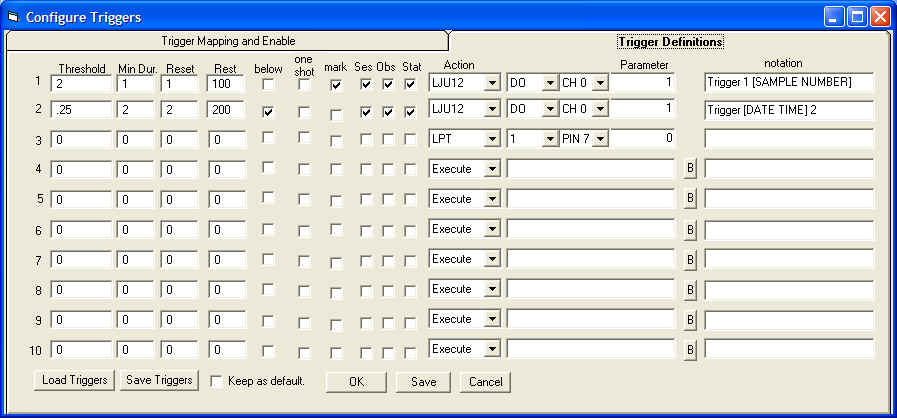
Triggers monitor the data being plotted in the strip chart and look for dips below or peaks above a set Threshold. The trigger then initiates a given Action. The action can be a physical output or the execution of software. The physical output can be manifested in either a LabJack USB device (model U3 or U12) or the setting of a state on a parallel port pin. The Execute Action starts a program or script on your computer. That executable file can be custom written in any programming or scripting language you please and perform whatever action you intend.
This description is a bit of a simplification. A number of other parameters must be set for the trigger to operate to its full potential.

What Activates a Trigger?
We have already said that a trigger is initiated by a chart value exceeding
(above or below) a set Threshold value. We set this Threshold in one of
the 10 trigger definitions on the Trigger Definitions tab of the Configure
Triggers window. If the trigger is activated by a level falling below
the threshold, then the corresponding check box in the 'below' column
must be checked. Otherwise it is assumed that the trigger is activated when the
level goes to or above the threshold.
There are several other parameters associated with each trigger.
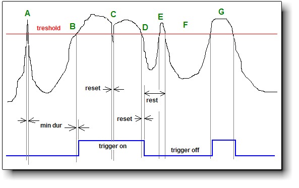
Minimum Duration (Min Dur) - This value determines the minimum duration that the threshold must be met or exceeded before the trigger is activated. The purpose of this parameter is to allow you avoid unwanted trigger activation due to short spikes in the data. The duration is measured in samples. For example, if we set Minimum Duration to 5 then we must receive 5 consecutive threshold exceeding samples to activate the trigger.
Reset - This parameter sets the number of consecutive samples that do not meet the threshold that will de-activate the trigger. For example, if a trigger has been activated and the level then falls below the threshold level for Reset number of samples, then the trigger will be de-activated.
Rest - sets the number of samples that must occur after a trigger is de-activated before that trigger can again be activated. The provides a way of regulating how frequently a trigger may be activated.

The chart above illustrates the various parameters involved in deciding
the trigger state (on or off - blue line).
The One Shot checkbox sets the Trigger to a single use mode where it can only be activated once during an observation.
The mark checkbox marks the chart using a chart notation using the format in the notation parameter (see below).
Ses places a notation in the Session Log using the format in the notation parameter (see below).
Obs places a notation in the Observer Log using the format in the notation parameter (see below).
Stat places a temporary notation in the Status Bar using the format in the notation parameter (see below).
The notation parameter determines the format and content of the mark, Ses, Obs, and Stat notations. You can use the tags DATE, TIME, and SAMPLE NUMBER, each in square brackets [ ]s. These will be replaced in the notations.
The Action parameter is set by selecting one of the following values:
LJU3 and LJU12 refer to the U3 and U12 Labjack ADC models that provide several digital outputs and 2 analog outputs that can be programmatically activated. When one of these Actions is selected there will appear two selection lists in the parameter column. The leftmost box will be AO or DO which stands for Digital Output and Analog Output, respectively. The right list allows selection of the appropriate channel on the Labjack module. For digital channels the channels will be CH1 to CHn. Analog channels will be DAC0 or DAC1 (DAC stands for digital to analog converter). In addition you must set a 1 or 0 in the parameter box for digital outputs or a voltage for analog outputs.
The Execute Action will start another program on the computer in response to a trigger. In this case the parameter will be the name of the executable file. A browse button allows you to search for the file on the computer.
LPT actions send an output to one of the printer port pins. The LPT number is selected from the leftmost selection box. The pin is selected in the right hand box and finally the state, a 1 or 0, is set as the final parameter.
Triggers can be saved or loaded in file form using the buttons at the bottom of the window. This allows you to develop arrays of triggers for different purposes. You may select any configuration of triggers to be the default.

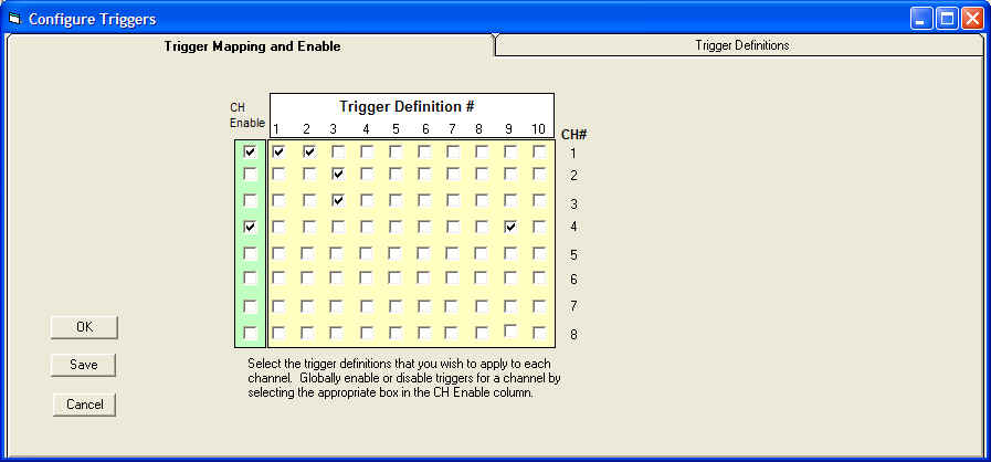
In the section above we discussed how to define triggers, that is, how set their threshold parameters and the actions they invoke. There are ten possible trigger definitions and these can be applied in any combination to any of the 8 available data channels. The Trigger Mapping and Enable tab on the Configure Triggers window provides for this.
Each channel has its own row on the grid. A checkbox appears in each row for each possible trigger definition. Simply select which triggers you wish to apply to the channel data. For example, in the picture above Trigger Definition #9 is being applied to channel 4.
On the left is a column of green check boxes that enable or disable the use of triggers for each channel. In the above example channels number 2 and 3 would never fire triggers even though they both have Trigger #3 mapped to them. Channels 1 and 4 would use their trigger definitions.